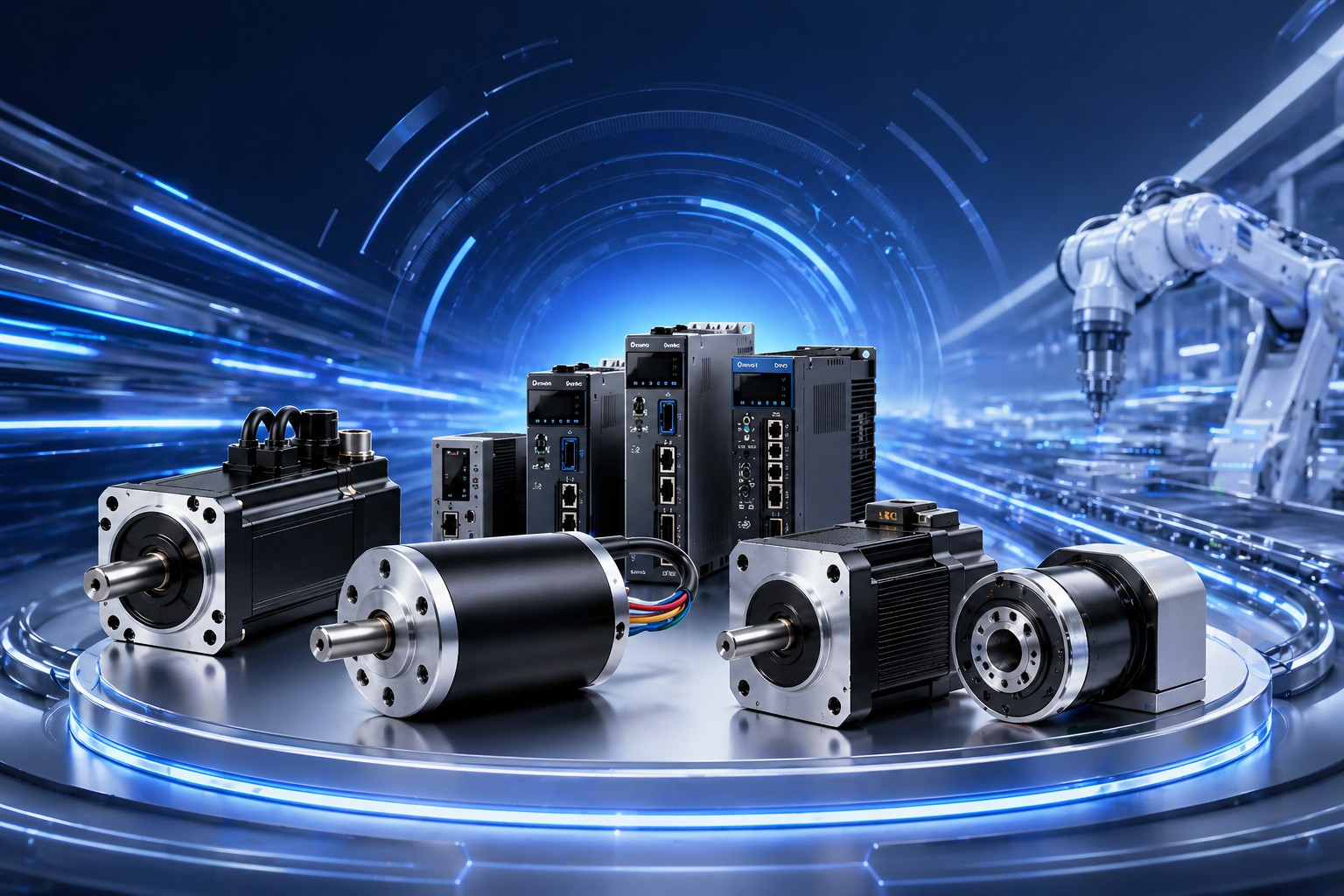
Servo Motor vs Stepper Motor: Which One Do You Actually Need?
When engineers debate motion control, the servo motor versus stepper motor argument comes up in nearly every project meeting. It’s not an academic question—choosing the wrong motor type can blow your budget by thousands of dollars, or worse, produce a machine that simply can’t meet its performance specs.
Table of Contents
- Why This Comparison Matters More Than You Think
- How Stepper Motors Actually Work
- How Servo Motors Actually Work
- Direct Performance Comparison
- Cost Analysis: Beyond the Motor Price Tag
- Application-Specific Recommendations
- The Rise of Closed-Loop Stepper Motors
- Motor Sizing and Selection: Practical Guidelines
- Common Mistakes and How to Avoid Them
- The Verdict: A Decision Framework
- Frequently Asked Questions
I’ve spent over a decade working with both motor types across industrial automation, robotics, and custom machinery. This guide cuts through the marketing fluff and gives you the technical grounding to make the right call for your specific application. We’ll cover the physics, the economics, and the practical gotchas that most datasheets won’t tell you.
Why This Comparison Matters More Than You Think

The global motion control market surpassed $21 billion in 2024, and both servo and stepper technologies are growing at 6-8% annually. But here’s what most people miss: the cost difference between these two options isn’t just about the motor itself. When you factor in the drive, cabling, encoder feedback, and the control complexity, a servo system can cost 3 to 10 times more than a comparable stepper setup.
That’s not a reason to default to steppers, though. The wrong motor type can lead to missed positioning accuracy, excessive heat generation, resonance problems, or outright system failures during critical operations. In high-throughput manufacturing environments, even a 2% positioning error translates to thousands of defective parts per shift.
So let’s get into the real differences—starting with the fundamental principles that govern how each motor converts electrical energy into mechanical motion.
How Stepper Motors Actually Work
The Basic Principle
A stepper motor operates on a deceptively simple concept: energize coils in a specific sequence, and the rotor moves in discrete angular increments called “steps.” Most common steppers use a permanent magnet rotor with teeth on both the rotor and stator. When current flows through a stator winding, it creates a magnetic field that attracts the nearest rotor teeth, causing rotation.
A standard hybrid stepper motor—the kind you’ll find in 3D printers, CNC machines, and automated stages—typically offers 200 steps per revolution. That’s 1.8° per step. Add microstepping (dividing each full step into smaller increments), and you can achieve resolutions of 25600 or more microsteps per revolution.
Step Angles and Resolution
The step angle is determined by the number of rotor teeth and stator phases. Common configurations include:
- 1.8° hybrid steppers (200 steps/rev): The workhorse of the industry, available in NEMA 17, 23, 34, and 42 frame sizes
- 0.9° stepper motors (400 steps/rev): Higher resolution at the cost of lower top speed
- 7.5° PM steppers (48 steps/rev): Rare in industrial applications, found mostly in consumer electronics and simple actuators
- 3.6° steppers: An uncommon middle ground with niche applications in valve control
The key insight about resolution is this: microstepping improves smoothness, not accuracy. A 256x microstep doesn’t give you 256 times better positioning accuracy. It gives you smoother motion and reduced vibration, but the fundamental detent torque and mechanical tolerances still limit your true accuracy to roughly ±5-10% of a full step.
Torque Characteristics
Stepper motors produce their highest torque at low speeds—what engineers call “holding torque.” As speed increases, the available torque drops off significantly due to the back-EMF opposing the driving current. This torque-speed curve is non-linear and depends heavily on the drive voltage and the motor’s inductance.
A typical NEMA 23 stepper rated at 3 N·m holding torque might deliver only 0.5 N·m at 1000 RPM. Push it to 2000 RPM, and you might be operating with minimal torque margin—a risky situation where a small load disturbance can cause missed steps.
This torque rolloff is one of the most critical factors in stepper motor selection. You need to examine the manufacturer’s pull-out torque curve (not just the holding torque spec) and ensure adequate torque margin at your operating speed.
Open-Loop vs Closed-Loop Steppers
Traditional stepper systems operate open-loop—no encoder feedback, no position correction. The controller simply sends step pulses and trusts that the motor follows. This works perfectly in many applications, but it creates a fundamental vulnerability: if the motor encounters a load that exceeds its available torque, it misses steps. And because there’s no feedback, the controller never knows it’s lost position.
Closed-loop stepper motors solve this by adding an encoder and a control loop that monitors actual rotor position. When a step error is detected, the drive adds correction pulses to catch up. In practice, this gives you:
- Position certainty: You always know where the motor actually is
- Higher usable torque: You can push the motor closer to its pull-out limit because the feedback loop catches errors
- No resonance-induced stalling: The system detects and corrects for resonance-induced position errors
- Better thermal management: The drive can reduce current when the motor is stationary or lightly loaded
Closed-loop steppers occupy a fascinating middle ground between traditional steppers and full servo systems, which we’ll explore in depth later.
How Servo Motors Actually Work

The Control Loop
A servo motor system is fundamentally a closed-loop control system. It consists of:
- The motor (typically a permanent magnet synchronous motor, or PMSM)
- An encoder (absolute or incremental) that measures rotor position
- A servo drive that converts command signals into motor currents
- A controller that generates position, velocity, or torque commands
The control loop operates at high frequency—typically 1-10 kHz or higher. At each iteration, the controller reads the actual position from the encoder, compares it to the commanded position, calculates an error, and adjusts the motor current to minimize that error. This happens thousands of times per second.
This closed-loop architecture is what gives servo motors their defining characteristic: accurate positioning under varying loads and across a wide speed range.
Torque Production: The Physics
Unlike stepper motors, which rely on the magnetic attraction between teeth, servo motors generate torque through the interaction of the rotor’s permanent magnets with the stator’s rotating magnetic field. The stator windings are driven by sinusoidal (or space-vector-modulated) currents, creating a smooth rotating field that “drags” the rotor along.
This continuous torque production has several advantages:
- Smooth rotation with minimal torque ripple (typically less than 3% peak-to-peak)
- High power density—servo motors produce more torque per unit volume than steppers
- Wide constant power speed range: The motor can operate at rated torque from zero speed up to the rated speed, then maintain constant power above rated speed through field weakening
The PID Controller and Tuning
The performance of a servo system depends critically on the PID (Proportional-Integral-Derivative) tuning. The P gain determines the stiffness of the response—how aggressively the system corrects position errors. The I gain eliminates steady-state error but can cause overshoot. The D gain dampens oscillations and improves stability.
Poorly tuned servo systems exhibit:
– Oscillation: The motor overshoots and oscillates around the target position
– Following error: A consistent position lag during motion
– Hunting: Small oscillations around the target when stationary
– Audible noise: Whining or buzzing from rapid current changes
Proper tuning is both an art and a science. Modern servo drives include auto-tuning algorithms that can get you 80-90% of the way there, but for demanding applications, manual fine-tuning by an experienced engineer is still the gold standard.
AC vs DC Servo Motors
Servo motors come in two main varieties:
AC Servo Motors: These are the dominant choice in industrial automation. They operate from 200V or 400V three-phase power, offer high power density, excellent thermal performance, and power ratings from 50W to over 100kW. The ZGC130SV200 series, for example, delivers 2000W in a 130mm frame with sophisticated encoder feedback.
DC Servo Motors: These operate from 12V, 24V, or 48V DC power supplies. They’re more compact, easier to integrate into battery-powered or vehicle-based systems, and well-suited for mobile robotics, AGVs, and smaller automation tasks. The ZGC60SV20 series provides 200W output at low voltage with high-precision 10-pole design.
Communication Protocols
Modern servo systems communicate with the motion controller through various protocols:
- Pulse/direction: Simplest interface, compatible with stepper controllers, limited bandwidth
- Analog voltage (±10V): Velocity or torque control, susceptible to noise
- CANopen: Industrial bus, supports daisy-chaining multiple drives, popular in Europe
- EtherCAT: High-speed Ethernet-based, sub-millisecond cycle times, increasingly dominant
- Modbus RTU/TCP: Widely available, slower, adequate for less demanding applications
Direct Performance Comparison
Speed
| Parameter | Stepper Motor | Servo Motor |
|---|---|---|
| Typical max speed | 1000-2000 RPM | 3000-6000 RPM |
| Speed range | Limited by torque rolloff | Flat torque curve to rated speed |
| Speed regulation | No inherent regulation | Typically ±0.1% or better |
Stepper motors lose torque rapidly at higher speeds due to inductive effects. At 2000 RPM, most steppers operate with minimal torque margin. Servo motors, by contrast, maintain rated torque across their full speed range (0 to rated speed), then transition to constant power operation above rated speed.
For applications requiring high-speed positioning—pick-and-place machines, packaging lines, high-speed CNC—servo motors are almost always the better choice.
Positioning Accuracy
| Parameter | Stepper Motor | Servo Motor |
|---|---|---|
| Open-loop accuracy | ±5% of step angle | N/A (always closed-loop) |
| Closed-loop accuracy | Encoder-limited (±0.05°) | Encoder-limited (±0.01° or better) |
| Repeatability | Good to excellent | Excellent |
With open-loop stepper operation, accuracy is fundamentally limited by the step angle and the potential for missed steps. A 1.8° stepper has a theoretical open-loop accuracy of about ±0.09° (±5% of full step), but real-world accuracy is typically worse due to friction, load variations, and resonance effects.
Closed-loop systems—whether closed-loop steppers or full servos—are limited by encoder resolution. A 20-bit encoder provides 1,048,576 counts per revolution, giving a theoretical resolution of about 0.0003°. Practical accuracy is limited by mechanical factors (backlash, compliance) rather than encoder resolution.
Torque
| Parameter | Stepper Motor | Servo Motor |
|---|---|---|
| Peak torque (instantaneous) | 2-3× rated (brief) | 3-5× rated (milliseconds) |
| Continuous torque | Limited by thermal rise | Rated continuous |
| Low-speed torque | Excellent | Good to excellent |
| High-speed torque | Poor | Excellent |
This is where the fundamental physics creates the clearest distinction. Stepper motors are strongest at standstill and weakest at high speed. Servo motors maintain flat torque across their speed range.
For applications like CNC cutting, where the spindle encounters varying cutting forces at different speeds, servo motors maintain consistent performance. For applications like wafer handling or inspection positioning, where movements are short and slow, stepper motors offer an excellent cost-to-performance ratio.
Dynamic Response
Dynamic response refers to how quickly and accurately a motor can follow a changing position or velocity command. This is measured by:
- Bandwidth: The frequency at which the system can track a sinusoidal command with less than -3dB attenuation
- Settling time: The time required to reach and stay within a specified position tolerance after a move
- Following error: The maximum position lag during constant velocity motion
Servo systems typically achieve bandwidths of 200-1000 Hz, while stepper systems (even closed-loop) rarely exceed 50-100 Hz. This means servos can make rapid, precise moves and handle high-acceleration profiles that would cause steppers to stall or miss steps.
Efficiency
Stepper motors are notably inefficient, especially when stationary. A stepper drive energizes two phases continuously to hold position, regardless of load. This means even a motor sitting still with zero external load may dissipate 50-80% of its rated power as heat.
Servo motors only draw the current needed to produce the demanded torque. When stationary, the current drops to near-zero (just enough to overcome static friction and maintain position against small disturbances). During motion, the drive continuously adjusts current to match the load, typically achieving overall efficiencies of 80-95% for the motor and drive combined.
For battery-powered applications or systems with tight thermal constraints, servo efficiency is a significant advantage.
Cost Analysis: Beyond the Motor Price Tag

Component-Level Costs
A stepper motor system requires:
– Stepper motor: $20-$200 depending on size
– Stepper drive: $30-$300
– Controller (pulse generator): Often integrated into PLC or motion controller
– Wiring: Simple, unshielded typically sufficient
A servo motor system requires:
– Servo motor with encoder: $150-$3,000+ depending on size and features
– Servo drive: $200-$2,000+
– Motion controller (or PLC with servo capability): $500-$5,000
– Wiring: Often shielded, sometimes with dedicated power cables
For a typical mid-range application (say, 400W output), the stepper solution might cost $200-500 total, while the servo solution might run $1,500-4,000. That’s a 3-8× cost difference.
Total Cost of Ownership
But the component price tells only part of the story. Consider:
Energy costs: A stepper system that holds position 24/7 wastes significant energy. Over a 5-year machine life, this can add up to hundreds or thousands of dollars in electricity—depending on motor size and duty cycle.
Machine downtime: A missed step in a stepper system can cause product defects, machine crashes, or unplanned downtime. If a single hour of downtime costs $500 (conservatively), and the stepper system causes 5 hours of downtime per year due to missed steps, that’s $2,500 per year in avoidable losses.
Development time: Open-loop stepper systems are simpler to configure and tune. Servo systems require PID tuning, which adds engineering time—typically 2-8 hours per axis for initial commissioning.
Maintenance: Stepper motors have no brushes or wearing parts (in the motor itself). Servo motors with encoders have more failure points, though modern sealed encoders are highly reliable.
When Steppers Are More Economical
Stepper motors win economically in these scenarios:
– Low-speed, high-torque applications where torque rolloff isn’t a factor
– Applications with constant, predictable loads
– Multi-axis systems where the cost multiplier per axis makes servos prohibitively expensive
– Prototyping and low-volume production where development speed matters more than peak performance
When Servos Are More Economical
Despite higher upfront costs, servos can be more economical when:
– The application requires high-speed operation (above 1500 RPM)
– Loads vary significantly during operation
– Position certainty is critical (pharmaceutical, semiconductor, medical devices)
– The machine operates continuously with high duty cycles (energy savings offset motor cost)
– Downtime costs are extremely high
Application-Specific Recommendations
CNC Machining
For CNC routers and milling machines, servo motors are the standard for professional and industrial machines. The combination of high-speed feed rates, varying cutting forces, and the need for precise contour following makes servos the clear choice.
However, many hobby-class and entry-level CNC machines use steppers successfully. If you’re cutting soft materials (wood, plastic, foam) at moderate speeds with light cuts, a NEMA 23 stepper system delivers excellent results at a fraction of the cost.
Robotics and Articulated Arms
Servo motors dominate in robotics. The dynamic motion profiles, varying inertial loads (as the arm moves, the effective inertia at each joint changes), and the need for precise coordinated multi-axis motion all point to servo systems.
The exception is in simple pick-and-place or SCARA robots with limited motion profiles, where closed-loop steppers can be an effective cost-reduction strategy.
3D Printing
3D printing is the stepper motor’s home turf. The speeds are low, the loads are light and predictable, and the cost sensitivity is extreme. Most 3D printers use NEMA 17 steppers on all axes.
The emerging trend toward faster 3D printing (CoreXY kinematics, high acceleration) is pushing the boundaries of stepper performance, and some high-end printers are beginning to use closed-loop steppers to maintain reliability at higher speeds.
Packaging Machinery
Packeting lines often involve dozens of axes of motion. At this scale, the cost difference between stepper and servo per axis becomes a dominant factor.
The typical approach is hybrid: servos for the critical motion axes (film feeding, cutting, product handling) where speed and precision matter, and steppers for auxiliary axes (conveyor drives, guide adjustments, gate actuators) where simpler motion suffices.
Automated Guided Vehicles (AGVs)
AGVs and mobile robots have unique requirements: battery power, limited space, and the need for smooth, quiet operation. Low-voltage DC servo motors are ideal here—they’re efficient (extending battery life), compact, and offer the smooth control needed for precise navigation.
Linear Motion Systems
For linear stages, ball screw drives, and linear actuators, the choice depends on the speed and precision requirements. High-speed linear stages (above 1 m/s) almost always use servos. Slow, high-precision positioning stages can work well with steppers, especially closed-loop versions.
The Rise of Closed-Loop Stepper Motors

Closed-loop stepper motors deserve special attention because they’re rapidly gaining market share and blurring the traditional boundary between stepper and servo systems.
How They Work
A closed-loop stepper adds an incremental or absolute encoder to the rear shaft of a standard stepper motor. The drive monitors the encoder feedback in real time and:
- Detects missed steps: If the encoder shows the motor hasn’t moved the expected number of steps, the drive adds correction pulses
- Optimizes current: The drive can reduce current when the motor is stationary (reducing heat) or increase current when extra torque is needed
- Prevents stalling: The system can detect an impending stall (when available torque approaches load torque) and either warn the controller or automatically adjust parameters
Closed-Loop Stepper vs True Servo
Despite the encoder feedback, closed-loop steppers are fundamentally different from servo motors:
| Feature | Closed-Loop Stepper | Servo Motor |
|---|---|---|
| Control algorithm | Step-following with correction | Full PID position/velocity loop |
| Torque production | Discrete (stepping) | Continuous (sinusoidal) |
| Smoothness at low speed | Good (microstepping) | Excellent |
| High-speed torque | Still limited | Excellent |
| Peak torque capability | Limited | High (3-5× rated) |
| Cost | Moderate | High |
| Tuning required | Minimal | Significant |
Closed-loop steppers fill a genuine gap in the market. They offer the simplicity and cost-effectiveness of stepper systems with the reliability assurance of feedback. For applications where traditional steppers work 95% of the time but occasionally miss steps due to load variations, closed-loop steppers eliminate that 5% failure mode at a modest cost increase.
When to Choose Closed-Loop Steppers
- Applications with occasional load transients that cause open-loop steppers to miss steps
- Systems requiring position verification for safety or quality reasons
- Multi-axis machines where the cost of full servos is prohibitive
- Retrofit projects where you want to improve reliability without redesigning the entire control system
Motor Sizing and Selection: Practical Guidelines
Step 1: Define Your Motion Profile
Before comparing motor types, you need to define what the motor actually needs to do:
- Maximum velocity: The highest speed the motor must achieve during operation
- Acceleration and deceleration: How quickly the motor must speed up and slow down
- Move distance: Total travel per motion cycle
- Duty cycle: Percentage of time the motor is in motion vs. stationary
- Load characteristics: Inertia, friction, external forces (gravity, cutting forces, etc.)
- Positioning accuracy: Required accuracy and repeatability at the load
Step 2: Calculate Torque Requirements
For a rotary motion profile, the required motor torque is:
T_motor = (J_load + J_motor) × α + T_friction + T_external
Where:
– J_load = load inertia reflected to the motor shaft
– J_motor = motor rotor inertia
– α = angular acceleration
– T_friction = friction torque
– T_external = any external forces (gravity, cutting, etc.)
For stepper motors, apply a safety factor of 1.5-2× on the required torque at the maximum operating speed (to account for torque rolloff and resonance).
For servo motors, apply a safety factor of 1.3-1.5× on peak torque and verify that the RMS torque over the duty cycle doesn’t exceed the continuous rating.
Step 3: Check Inertia Matching
For servo systems, the inertia ratio (load inertia / motor inertia) is critical:
- Ratio < 5:1: Excellent dynamic response, easy tuning
- Ratio 5:1 to 10:1: Good, may require careful tuning
- Ratio > 10:1: Challenging, requires gearbox or larger motor
Stepper systems are more forgiving of inertia mismatch because they operate in open loop (or with simple step correction), but excessive load inertia can still cause missed steps during rapid acceleration.
Step 4: Verify Thermal Performance
Ensure the motor can dissipate the heat generated during operation. Calculate the RMS current over the duty cycle and verify that the motor’s thermal rating is adequate. For servo motors, this is straightforward—the drive automatically manages current. For stepper motors, you may need to derate the current at elevated ambient temperatures or consider forced air cooling.
Common Mistakes and How to Avoid Them

Mistake 1: Oversizing Stepper Motors
It’s tempting to select a stepper motor with much more torque than needed “just to be safe.” This usually backfires because larger stepper motors have higher inertia, which limits acceleration and makes resonance problems worse. The right approach is to select the smallest motor that meets your torque requirements with the appropriate safety factor.
Mistake 2: Ignoring Resonance
Stepper motors have natural resonance frequencies where they can lose significant torque or even stall. These frequencies depend on the motor characteristics, load inertia, and drive configuration. Avoid operating at resonance frequencies, and use microstepping to reduce resonance effects.
Mistake 3: Underestimating Cable Length Effects
Long motor cables can cause signal degradation (stepper pulse distortion) and voltage drops. For stepper systems, keep cable lengths under 5 meters for reliable operation at high step rates. For servo systems, use the manufacturer’s recommended cable specifications and consider cable extensions or repeaters for runs over 25 meters.
Mistake 4: Neglecting Grounding and Shielding
Servo drives generate significant electrical noise, particularly during high-speed switching. Poor grounding and shielding can cause erratic behavior, communication errors, and even damage sensitive electronics. Follow the manufacturer’s grounding recommendations rigorously.
Mistake 5: Choosing Based on Price Alone
The cheapest motor that meets the torque spec isn’t necessarily the most economical choice. Consider the total cost of ownership: energy consumption, reliability, development time, maintenance requirements, and the cost of system failures.
The Verdict: A Decision Framework
Rather than a simple “servo vs stepper” answer, here’s a practical decision tree:
Choose a stepper motor when:
– Operating speed is below 1000 RPM
– Load is constant and predictable
– Positioning accuracy of ±0.1° is acceptable
– Multi-axis system (cost sensitivity per axis)
– Application has low duty cycle (energy waste is tolerable)
– Development timeline is tight (simpler setup)
Choose a closed-loop stepper when:
– You’d choose a stepper, but need position certainty
– Occasional load transients might cause missed steps
– You need stall detection for safety
– Cost matters more than peak dynamic performance
Choose a servo motor when:
– Operating speed exceeds 1500 RPM
– Wide speed range required
– Load varies significantly during operation
– Positioning accuracy better than ±0.05° required
– High duty cycle (energy efficiency matters)
– Complex motion profiles (contouring, electronic gearing, camming)
– Downtime cost is very high
Frequently Asked Questions
Can a stepper motor hold position without power?
No. When power is removed, a stepper motor provides no holding torque (unless it’s equipped with a brake). The rotor will move if an external force is applied. Servo motors have the same limitation.
Is microstepping worth it?
For smoothness and reduced vibration, absolutely. For improved accuracy, only marginally—the fundamental step size and mechanical tolerances still limit true accuracy. Most applications benefit from 16x to 64x microstepping. Going beyond 256x provides diminishing returns.
Can I replace a stepper with a servo without changing the drive?
No. Stepper drives and servo drives are fundamentally different. However, some closed-loop stepper drives accept standard step/direction inputs, so you can upgrade from open-loop to closed-loop stepper without changing the controller.
How do I know if my stepper is missing steps?
Without a closed-loop system, you can’t know for sure. Indirect indicators include: the machine produces intermittent quality issues, the home position drifts over time, or you hear abnormal sounds during high-speed moves. Adding a simple home switch for re-homing between cycles can mitigate the consequences.
What’s the lifespan of a servo motor vs stepper motor?
Both types typically last 20,000-50,000+ hours in industrial applications. The primary failure modes are bearing wear (both types) and encoder failure (servo only). Stepper motors have no encoder to fail, which gives them a slight reliability edge in harsh environments.
Can servo motors run in open loop?
Technically yes, but it defeats the purpose. A servo motor without feedback operates as an inefficient brushless DC motor with no position control. There’s rarely a reason to do this.
Do I need a gearbox with my servo motor?
Not always, but often. A gearbox reduces the reflected load inertia (improving the inertia ratio), increases torque at the load, and allows a smaller, faster motor to drive a high-torque load. Planetary gearboxes are the most common choice for servo applications due to their compact size, high efficiency, and low backlash.
How important is the encoder resolution in a servo system?
More important for smoothness at low speed than for static accuracy. A 17-bit encoder (131,072 counts/rev) provides more than enough accuracy for most industrial applications. Higher resolutions (20-bit, 23-bit) help with velocity ripple at very low speeds but add cost.
Need Help Selecting the Right Motor?
ZGC Motors offers a complete range of BLDC motors, servo motors, stepper motors, and motor controllers for industrial, automotive, and outdoor power applications. Our engineering team can help you find the perfect solution for your project.