High-performance servo motor for precision automation and robotics. Get a free quote from ZGC Motors, a trusted servo motor manufacturer.
High-performance servo motor for precision automation and robotics. Get a free quote from ZGC Motors, a trusted servo motor manufacturer.
Various electronic processing equipment, assembly line material transfer devices, medical equipment, instrumentation, precision testing equipment, channel gate control, Cartesian coordinate robots, servo fixed-length positioning, garage blocking control, equipment loading and unloading devices, equipment auxiliary motion devices, grasping picking and handling machinery, inkjet printers, photo machines, home and office automation equipment, etc.
Utilizes FOC (Field Oriented Control) technology and SVPWM (Space Vector Pulse Width Modulation) algorithm. Easily modify motor parameters to adapt to various motor specifications. Built-in electronic gears and graphical debugging software. Custom control functions available upon user request.
| 1. Basic Parameters | Input Power: | Three-phase AC 220V |
| Control Methods: | Position Control, Speed Control, Torque Control | |
| 2. Operating Environment | Operating Temp/Humidity: | 0~40℃; 40%~80% RH (no condensation) |
| Storage Temp/Humidity: | -40~50℃; ≤80% RH (no condensation) | |
| Vibration: | ≤0.5G | |
| Atmospheric Pressure: | 86-106kPa | |
| Installation Site: | Well-ventilated, low moisture/dust; free of corrosive/flammable gases, oil fumes; no moisture or direct sunlight | |
| 3. Core Features | Speed Frequency Response: | ≥200Hz |
| Speed Fluctuation: | <±0.03% (load 0~100%); <±0.02% (power supply -15%~+10%) | |
| Speed Regulation Ratio: | 1:3000 | |
| Pulse Frequency: | ≤500kHz | |
| Control Input: | Servo Enable, Alarm Reset, CCW Drive Inhibit, CW Drive Inhibit, Homing Control | |
| Control Output: | Servo Ready Output, Servo Alarm Output, Position Completion Output, Mechanical Brake Output | |
| Position Control: | Input Modes (Pulse+Sign/CW Pulse+CCW Pulse/2-Phase A/B Quadrature Pulse/Communication Command); Electronic Gear (1-1000/1-1000) | |
| Speed Control: | Analog Speed Control, Communication Speed Control | |
| Acceleration/Deceleration: | Configurable (1-1000ms/1000min) | |
| Monitoring Functions: | Rotational Speed, Motor Torque, Motor Current, Command Pulse Frequency, Voltage, Alarms, etc. | |
| 4. Installation Requirements | Installation Orientation: | Preferred vertical upright |
| Horizontal Installation: | Route cable outlets downward (to prevent liquid from entering the motor) | |
| Vertical Installation (with gearbox): | Prevent gearbox oil from seeping into the motor shaft | |
| Motor Shaft: | Ensure sufficient extension (to avoid vibration during operation) | |
| Note: Do not strike the motor with a hammer during installation/removal (to prevent shaft/encoder damage) | ||
| 5. Wiring Specifications | Wire Gauge: | R, S, T, U, V, W, PE terminals ≥ 1.5mm² (AWG14-16); r, t terminals≥0.75mm² (AWG18) |
| Terminals: Use pre-insulated crimp terminals; ensure secure connections | ||
| 6. Protection Functions | Overvoltage Protection, Undervoltage Protection, Short-Circuit Protection, Drive Overheating Protection, Overload Protection, Overcurrent Protection, Excessive Position Error, Encoder Fault, Alarm Output | |
| Function | Servo Drive Model | ||||||||
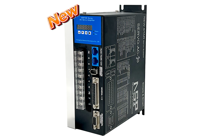
| Hardware Parameters | NSP-SERVO | DC-01 | DC-02 | DC-05 | DC-10 | DC-20 | AC-10 | AC-30 | |
| Input Voltage | DC18-60V | ✔ | ✔ | ✔ | ✔ | ✔ | |||
| AC90-265V | ✔ | ✔ | |||||||
| Input Power | DC-100W | ✔ | |||||||
| DC-200W | ✔ | ||||||||
| DC-500W | ✔ | ||||||||
| DC-1000W | ✔ | ||||||||
| DC-2000W | ✔ | ||||||||
| AC-1000W | ✔ | ||||||||
| AC-2000W | |||||||||
| AC-3000W | ✔ | ||||||||
| Output Speed | 1-3500 RPM | ✔ | ✔ | ✔ | ✔ | ✔ | ✔ | ✔ | |
| Hardware Functions | Potentiometer Input | 0-5V | ✔ | ✔ | ✔ | ✔ | ✔ | ✔ | ✔ |
| Enable Input | Differential Level | ✔ | ✔ | ✔ | ✔ | ✔ | ✔ | ✔ | |
| Pulse Input | Differential Level | ✔ | ✔ | ✔ | ✔ | ✔ | ✔ | ✔ | |
| Direction | Forward Input | ✔ | ✔ | ✔ | ✔ | ✔ | ✔ | ✔ | |
| Reverse Input | ✔ | ✔ | ✔ | ✔ | ✔ | ✔ | ✔ | ||
| Encoder Input | Incremental Differential Input | ✔ | ✔ | ✔ | ✔ | ✔ | ✔ | ✔ | |
| Communication Absolute Value | ✔ | ✔ | ✔ | ✔ | ✔ | ✔ | ✔ | ||
| Encoder Output | Differential Output | ✔ | ✔ | ✔ | ✔ | ✔ | ✔ | ✔ | |
| ✔ | ✔ | ✔ | ✔ | ✔ | ✔ | ✔ | |||
| Clear Input | Active Low | ✔ | ✔ | ✔ | ✔ | ✔ | ✔ | ✔ | |
| Zero Point Input | Active Low | ✔ | ✔ | ✔ | ✔ | ✔ | ✔ | ✔ | |
| Brake Output | Active High | ✔ | ✔ | ✔ | ✔ | ✔ | ✔ | ✔ | |
| Position Output | Active High | ✔ | ✔ | ✔ | ✔ | ✔ | ✔ | ✔ | |
| Ready Output | Active High | ✔ | ✔ | ✔ | ✔ | ✔ | ✔ | ✔ | |
| Fault Output | Active High | ✔ | ✔ | ✔ | ✔ | ✔ | ✔ | ✔ | |
| Communication Interface | USB Interface | ✔ | ✔ | ✔ | ✔ | ✔ | |||
| RS232 Interface | ✔ | ✔ | ✔ | ✔ | ✔ | ✔ | ✔ | ||
| RS485 Interface | ✔ | ✔ | ✔ | ✔ | ✔ | ✔ | ✔ | ||
| CAN Interface | ✔ | ✔ | ✔ | ✔ | ✔ | ✔ | ✔ | ||
| Termination Resistor | ✔ | ✔ | ✔ | ✔ | ✔ | ✔ | ✔ | ||
| Panel Display | ✔ | ✔ | ✔ | ✔ | ✔ | ||||
| Host Computer Debugging | ✔ | ✔ | ✔ | ✔ | ✔ | ✔ | ✔ | ||
| Software Functions | Position Mode – External Pulse Input | ✔ | ✔ | ✔ | ✔ | ✔ | ✔ | ✔ | |
| Position Tuning Mode – PC Digital Input | ✔ | ✔ | ✔ | ✔ | ✔ | ✔ | ✔ | ||
| Position Control Mode – External Analog Input | ✔ | ✔ | ✔ | ✔ | ✔ | ✔ | ✔ | ||
| Speed Control Mode – External Analog Input | ✔ | ✔ | ✔ | ✔ | ✔ | ✔ | ✔ | ||
| Speed Tuning Mode – PC Digital Input | ✔ | ✔ | ✔ | ✔ | ✔ | ✔ | ✔ | ||
| Torque Control Mode – External Analog Input | ✔ | ✔ | ✔ | ✔ | ✔ | ✔ | ✔ | ||
| Torque Tuning Mode – PC Digital Input | ✔ | ✔ | ✔ | ✔ | ✔ | ✔ | ✔ | ||
| Jog Speed Mode | ✔ | ✔ | ✔ | ✔ | ✔ | ✔ | ✔ | ||
| Key Speed Mode | ✔ | ✔ | ✔ | ✔ | ✔ | ✔ | ✔ | ||