Brushless DC motors—commonly known as BLDC motors—have transformed the way engineers and designers approach motion control across virtually every industry. From the drone hovering above a construction site to the electric vehicle quietly accelerating on the highway, from the industrial robot arm assembling semiconductors to the garden tool trimming a lawn, BLDC motors are the invisible workhorses powering the modern world.
Yet despite their ubiquity, many buyers, engineers, and procurement professionals still carry misconceptions about what a BLDC motor actually is, how it differs from its brushed counterpart, and which type best suits a given application. This guide cuts through the noise. By the time you finish reading, you will understand the physics, the engineering, the practical selection criteria, and the latest innovations shaping BLDC motor technology in 2025 and beyond.
Whether you are sourcing a BLDC motor for a new product design, evaluating suppliers, or simply deepening your technical knowledge, this is the most comprehensive reference you will find.
Table of Contents
- What Is a BLDC Motor?
- How Does a Brushless DC Motor Work?
- BLDC Motor vs Brushed DC Motor: Key Differences
- BLDC Motor vs AC Motor: When to Choose Which
- Types of BLDC Motors
- Key Specifications Explained
- BLDC Motor Controllers and Drivers
- FOC vs Trapezoidal Control
- Applications of BLDC Motors
- How to Select the Right BLDC Motor
- BLDC Motor Maintenance and Lifespan
- BLDC Motor Trends in 2025
- FAQ: Common Questions Answered
1. What Is a BLDC Motor? {#what-is-a-bldc-motor}

A brushless DC motor (BLDC motor) is an electrically commutated synchronous motor powered by direct current. Unlike traditional brushed DC motors that use physical carbon brushes and a mechanical commutator to switch current direction, a BLDC motor relies entirely on electronic switching—typically handled by a dedicated BLDC motor controller or BLDC motor driver—to commutate the stator windings in the correct sequence.
The result is a motor that delivers the speed controllability and torque characteristics associated with DC power, combined with the reliability and longevity more typically seen in AC induction motors.
A Quick Historical Perspective
The brushless DC motor concept emerged in the 1960s as semiconductor technology matured sufficiently to make electronic commutation practical. Early adopters were aerospace and military applications where cost was secondary to reliability and performance. By the 1980s, dropping transistor costs brought BLDC motors into industrial servo drives. The consumer electronics revolution of the 1990s and 2000s—hard drives, cooling fans, optical drives—drove volumes into the billions. Today, the electric vehicle and robotics booms have pushed BLDC motor technology into a new era of sophistication.
Why “DC” If There Are No Brushes?
The “DC” in BLDC refers to the power source: a direct current supply. Internally, however, the motor creates a rotating magnetic field through electronically switched AC-like currents in the stator windings. The name is therefore a legacy of the motor’s functional equivalence to brushed DC motors rather than a strict description of its internal workings.
2. How Does a Brushless DC Motor Work? {#how-does-a-bldc-motor-work}

Understanding BLDC motor operation requires grasping three interrelated concepts: the physical structure, the magnetic interaction that produces torque, and the electronic commutation system that coordinates it all.
2.1 Physical Structure
A BLDC motor consists of two primary assemblies:
The Stator (Stationary Part)
The stator is the outer, non-rotating component. It contains the armature windings—coils of copper wire arranged in slots cut into a laminated silicon steel core. Most BLDC motors use a three-phase winding configuration, with the three phases labeled U, V, and W (or A, B, C). The number of poles in the stator winding determines the motor’s base electrical frequency for a given mechanical speed.
The Rotor (Rotating Part)
In a BLDC motor, the rotor carries the permanent magnets. This is the inverse of a brushed DC motor, where the armature (coils) rotates and the field magnets are stationary. Common rotor magnet materials include ferrite for cost-sensitive applications and neodymium iron boron (NdFeB) for high-performance designs requiring maximum torque density.
The rotor design splits into two main configurations:
– Inner rotor: Magnets are on a cylinder inside the stator. This is the most common configuration, offering faster dynamic response due to lower rotor inertia.
– Outer rotor (hub motor): The rotor forms a shell that surrounds the stator. This geometry provides higher torque at lower speeds and is common in fans, direct-drive wheels, and drone propulsion.
Position Sensors
Most BLDC motors include Hall effect sensors embedded in the stator. These sensors detect the rotor magnet position and feed position data to the motor controller, enabling it to switch the stator phases at the correct moment. Sensorless BLDC motors exist and use back-EMF (electromotive force) detection instead, which works well at moderate to high speeds but struggles at startup and very low speeds.
2.2 Torque Production: The Lorentz Force
Torque in any electric motor arises from the interaction between a magnetic field and a current-carrying conductor. When current flows through a stator winding in the presence of the rotor’s permanent magnetic field, a Lorentz force acts on the conductor. In a three-phase BLDC motor, three sets of windings are energized in a controlled sequence so that the force vectors sum to produce smooth, continuous rotational torque.
The torque equation for a BLDC motor is:
T = K_t × I
Where:
– T = Torque (N·m)
– K_t = Motor torque constant (N·m/A), determined by winding design and magnet strength
– I = Phase current (A)
This linear relationship between torque and current is one of the key advantages of BLDC motors: torque is predictable and easily controllable by regulating current.
2.3 Electronic Commutation
Commutation is the process of switching current through the stator windings in the correct sequence to maintain optimal alignment between the stator magnetic field and the rotor magnets—maximizing torque production throughout the rotation.
In a brushed motor, this switching is done mechanically by the commutator and brushes. In a BLDC motor, it is done electronically by the motor driver, which uses six power transistors (typically MOSFETs or IGBTs) arranged in a three-phase bridge circuit. The controller reads the Hall sensor signals (or back-EMF signals in sensorless designs) and fires the transistors in the correct sequence.
The most basic commutation strategy, called six-step (trapezoidal) commutation, energizes two of the three phases at a time in six discrete steps per electrical revolution. More advanced Field Oriented Control (FOC) continuously optimizes the current vector to maximize torque and minimize losses—we will cover this in depth in Section 8.
2.4 Speed Control
BLDC motor speed is controlled by varying the voltage applied to the windings, typically achieved through Pulse Width Modulation (PWM). The controller rapidly switches the supply voltage on and off at a frequency of 10–100 kHz, with the duty cycle (ratio of on-time to total period) determining the effective voltage. Higher duty cycle = higher voltage = higher speed. Closed-loop speed control uses the position sensor feedback to continuously compare actual speed to the target and adjust the PWM accordingly.
3. BLDC Motor vs Brushed DC Motor: Key Differences {#bldc-vs-brushed}
The transition from brushed to brushless technology was not arbitrary—it was driven by compelling engineering advantages. Here is a systematic comparison:
3.1 Efficiency
Brushed DC motors lose energy through brush friction and the resistive losses in the rotor windings (which carry full load current). BLDC motors move the copper windings to the stator, where they are easier to cool, and eliminate brush friction entirely. The result: BLDC motors typically achieve 85–95% efficiency compared to 75–85% for equivalent brushed motors. In battery-powered applications, this difference directly translates to longer runtime.
3.2 Lifespan and Reliability
Carbon brushes wear down over time. In a heavily loaded motor, brushes may need replacement every 1,000–3,000 hours. BLDC motors have no brushes, no commutator wear, and the only mechanical wear points are the bearings—which can be designed for 20,000–50,000 hours of service life. This makes BLDC motors the obvious choice for applications where maintenance access is difficult or costly.
3.3 Power Density
Because the heat-generating windings are in the stator (which can be cooled externally), BLDC motors can be designed with higher current density and therefore higher power output per unit weight and volume. A high-performance BLDC motor might produce 5–10 kW/kg, compared to 2–4 kW/kg for a brushed equivalent.
3.4 Noise and EMI
Brush arcing generates both acoustic noise and electromagnetic interference (EMI)—a serious problem in sensitive electronics applications. BLDC motors produce dramatically less EMI, making them suitable for medical devices, precision instruments, and aerospace electronics.
3.5 Speed Range
Brushed motors are limited in maximum speed by brush contact quality at high RPM. BLDC motors can operate at extremely high speeds (100,000+ RPM in some designs) limited only by bearing capability and centrifugal stress on the rotor magnets.
3.6 Cost
The primary disadvantage of BLDC motors is higher upfront cost. A BLDC motor requires a controller/driver that a brushed motor does not, adding both component cost and system complexity. For high-volume, low-duty-cycle applications where brush life is sufficient, brushed motors remain cost-competitive.
| Parameter | BLDC Motor | Brushed DC Motor |
|---|---|---|
| Efficiency | 85–95% | 75–85% |
| Service life | 20,000–50,000 hrs | 1,000–3,000 hrs (brush limited) |
| Power density | High | Medium |
| EMI | Low | Higher (brush arcing) |
| Max speed | Very high | Moderate |
| Maintenance | Minimal | Regular brush replacement |
| Control complexity | High (requires driver) | Low |
| Cost | Higher | Lower |
4. BLDC Motor vs AC Motor: When to Choose Which {#bldc-vs-ac}
Both BLDC motors and AC induction motors are widely used in industrial applications. Understanding when each is appropriate is critical for system optimization.
AC Induction Motors: Strengths and Limitations
AC induction motors are the workhorses of industry—rugged, inexpensive, and available in enormous size ranges. They run directly from AC mains power without a dedicated drive (though variable speed requires a Variable Frequency Drive, or VFD). Their limitations include:
– Lower efficiency, especially at partial load (70–90% vs 85–95% for BLDC)
– Poor low-speed torque without a VFD
– No inherent position control capability without encoders
– Rotor copper/aluminum losses (slip losses)
BLDC Motors: Where They Win
BLDC motors excel where AC motors struggle:
– Precise speed control over a wide range without expensive VFDs
– High torque at low speed for servo-like performance
– Compact, high-power-density installations
– Battery-powered systems where efficiency is paramount
– Positioning and servo applications with integrated feedback
Permanent Magnet Synchronous Motors (PMSM)
It is worth noting that PMSM motors (Permanent Magnet Synchronous Motors) are closely related to BLDC motors—both use permanent magnet rotors and electronic commutation. The distinction is primarily in the back-EMF waveform: BLDC motors have a trapezoidal back-EMF (suited to six-step commutation) while PMSMs have sinusoidal back-EMF (suited to FOC/sinusoidal commutation). Modern motor controllers can drive both types effectively, and the boundary between BLDC and PMSM has blurred considerably.
5. Types of BLDC Motors {#types-of-bldc-motors}

BLDC motors come in a wide variety of configurations. Selecting the right type requires understanding both mechanical and electrical variants.
5.1 By Rotor Position
Inner Rotor BLDC Motor
The most common configuration. The rotor sits inside the stator bore. Advantages include:
– Lower rotor inertia → faster acceleration and response
– Better thermal performance (stator heat dissipates to housing)
– Compact form factor
– Wide speed range
Applications: Servo drives, robotics, precision machinery, pumps, compressors.
ZGC’s inner rotor BLDC motors cover power ranges from 100W to 10kW with peak torque densities up to 8 N·m/kg.
Outer Rotor BLDC Motor
The rotor forms a bell-shaped shell that surrounds the stator. Advantages include:
– Higher pole count possible → higher torque at lower speed
– Larger rotor diameter → better utilization of magnet volume
– Natural integration with fan blades or wheel hubs
Applications: Drone propulsion, cooling fans, direct-drive wheels, wind turbines, e-bikes.
ZGC’s outer rotor BLDC motors are engineered for high-torque direct-drive applications with peak efficiency above 92%.
5.2 By Feedback Type
Hall Sensor BLDC Motors
Three Hall effect sensors detect rotor position at 60° electrical intervals. This provides reliable startup torque and stable low-speed operation. The tradeoff is added wiring complexity and sensor failure risk.
Sensorless BLDC Motors
Position is estimated from back-EMF zero-crossing detection. Simpler mechanically, but struggles at zero and very low speed. Common in fans, pumps, and other applications where startup torque requirements are modest.
Encoder-Equipped BLDC Motors
For precision servo applications, optical or magnetic encoders with 1,000–10,000+ pulses per revolution provide high-resolution position feedback. This is the configuration used in motor with encoder servo systems and closed-loop positioning.
5.3 By Frame Size
BLDC motors follow standard frame size conventions (NEMA or IEC). Common sizes used in industrial and automation applications:
- NEMA 17 / 42mm: Small motors for light-load robotics, 3D printers, small actuators (typically 50–200W)
- NEMA 23 / 57mm: Medium-duty automation, conveyor systems (200–800W)
- NEMA 34 / 86mm: Heavy-duty CNC, industrial robotics (500W–3kW)
- Large frames (100mm+): Industrial drives, EV traction, heavy automation (3–50kW+)
5.4 Integrated Motor-Drive Units
Integrated motor drive (also called servo drive integrated motor or closed-loop motor) combines the motor, encoder, and driver electronics in a single compact package. Benefits include:
– Reduced wiring complexity
– Better EMI management (signals stay internal)
– Space savings in machine design
– Factory-tuned performance parameters
ZGC’s integrated motor-drive series offers plug-and-play solutions compatible with common industrial protocols including CAN, RS485, and pulse/direction interfaces.
6. Key Specifications Explained {#key-specifications}
Reading a BLDC motor datasheet requires understanding a set of standardized parameters. Here is a comprehensive guide to the most important specifications.
6.1 Rated Voltage (V)
The DC bus voltage for which the motor is designed. Common values: 12V, 24V, 36V, 48V, 72V, 96V, 310V (rectified 220VAC). Higher voltage allows lower current for the same power, reducing wiring losses.
6.2 Rated Power (W or kW)
Continuous output mechanical power at rated speed and torque. Note: peak power can be 2–3× rated power for short durations.
6.3 Rated Speed (RPM)
Mechanical rotational speed at rated voltage and no-load or rated load condition. Distinguish between:
– No-load speed: Maximum speed with zero torque load
– Rated speed: Speed at rated power output
– Maximum speed: Absolute upper limit (may be thermally or mechanically limited)
6.4 Rated Torque (N·m)
Continuous torque output at rated conditions. Key derived metrics:
– Peak torque: Short-term maximum, typically 2–3× rated torque
– Stall torque: Torque at zero speed (motor blocked)—important for servo hold applications
– Torque constant (K_t): N·m per ampere of phase current
6.5 Back-EMF Constant (K_e)
Voltage generated per unit speed (V/RPM or V·s/rad). Related to torque constant by: K_e = K_t (in consistent SI units). Higher K_e means higher voltage per RPM and lower current per torque—generally favorable for efficiency.
6.6 Phase Resistance (Ω)
DC resistance of each stator winding phase. Determines copper losses (I²R) and affects thermal performance. Lower resistance = less heat at rated current.
6.7 Pole Pairs
Number of magnetic pole pairs on the rotor. More poles = higher torque at lower electrical frequency = smoother rotation at low mechanical speed. Standard BLDC motors have 2–12 pole pairs. High-torque direct-drive motors may have 20+ pole pairs.
6.8 Thermal Resistance and Maximum Winding Temperature
Defines how quickly heat transfers from windings to ambient. Maximum winding temperature (typically 125°C–180°C depending on insulation class) sets the continuous power limit in a given thermal environment.
6.9 Ingress Protection (IP Rating)
Defines environmental sealing:
– IP40: No dust protection, no water protection. Indoor use only.
– IP54: Dust limited ingress, splash protection
– IP65: Dust-tight, low-pressure water jet resistant. Common industrial standard.
– IP67: Dust-tight, immersion to 1m for 30 minutes. For outdoor and wet environments.
– IP68: Continuous immersion rated. For fully waterproof BLDC motors.
6.10 Efficiency Map
High-quality datasheets include an efficiency map—a 2D plot of torque vs. speed with efficiency contours overlaid. This is essential for optimizing system design, as BLDC motor efficiency varies significantly across the operating envelope.
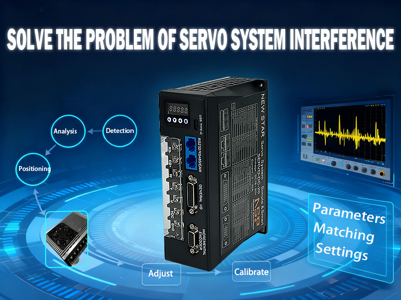
7. BLDC Motor Controllers and Drivers {#controllers-and-drivers}
The BLDC motor controller (also called BLDC motor driver or brushless motor drive) is an inseparable part of any BLDC motor system. No BLDC motor can run without one. Understanding controllers is therefore essential to system selection.
7.1 Core Controller Functions
A BLDC motor controller performs several critical functions:
- Commutation logic: Reads Hall sensor (or back-EMF) signals and switches the power bridge transistors in the correct sequence
- Current control: Regulates phase current to achieve target torque
- Speed control: Implements closed-loop PID or more advanced algorithms to maintain target speed
- Protection: Over-current, over-voltage, under-voltage, over-temperature, short-circuit, and stall protection
- Communication: Interface with host system via analog signals (0–5V, 4–20mA), PWM, RS485/Modbus, CAN bus, or digital pulse/direction commands
7.2 Power Stage Design
The heart of the controller is a three-phase full-bridge circuit using six power transistors:
– MOSFETs: Preferred for voltages below 100V. Lower conduction losses, faster switching, simpler gate drive.
– IGBTs: Better suited for higher voltages (200V+). Higher conduction losses but better suited to hard switching at higher currents.
Modern controllers use intelligent power modules (IPMs) that integrate the transistors, gate drivers, and protection circuits into a single component, improving reliability and reducing PCB area.
7.3 Controller Selection Criteria
When selecting a BLDC motor controller, consider:
Voltage and current ratings: Must exceed motor’s maximum values with appropriate derating margin (typically 20–30% headroom).
Control mode: Does your application need speed control only, or torque and position control as well? Servo-grade controllers support all three loops.
Communication protocol: Match the controller to your system’s communication bus—analog, PWM, RS485/Modbus, CAN, EtherCAT, or pulse/direction.
Feedback compatibility: Hall sensor inputs? Encoder inputs (incremental or absolute)? Resolver? The controller must support your motor’s feedback type.
Form factor: Standalone driver vs. integrated PCB vs. built-in motor? DIN rail mount for panel installation?
Operating environment: Temperature range, IP rating if exposed to moisture or dust.
7.4 ZGC BLDC Motor Controller Options
ZGC offers a complete range of brushless motor drive solutions designed to complement our motor lineup:
- Compact 24V–48V drivers: For robotics and automation applications under 1kW
- 48V–72V mid-range controllers: 1kW–5kW range for industrial machinery
- High-power 72V–96V controllers: 5kW–20kW for heavy-duty applications
- Integrated motor-drive modules: All-in-one solutions for simplified system integration
All ZGC controllers feature Hall sensor and encoder inputs, RS485/Modbus communication, and comprehensive motor protection.
8. FOC vs Trapezoidal Control {#foc-vs-trapezoidal}

The commutation algorithm used by the motor controller has a dramatic impact on BLDC motor performance. The two dominant approaches—trapezoidal (six-step) and Field Oriented Control (FOC)—each have distinct characteristics.
8.1 Trapezoidal (Six-Step) Commutation
In six-step commutation, the controller energizes two of three phases at a time, cycling through six discrete switching states per electrical revolution.
Advantages:
– Simple to implement—minimal computational requirements
– Works reliably with basic Hall sensors
– Robust at high speeds
– Low-cost controller implementation
Disadvantages:
– Torque ripple: At each commutation step, there is a transient torque disturbance (~15–30% ripple)
– Audible noise from commutation steps
– Lower efficiency, particularly at partial load
– Not suitable for precision positioning
8.2 Field Oriented Control (FOC)
FOC (also called vector control) treats the motor as a system of rotating magnetic flux vectors. Using real-time mathematical transformations (Clarke and Park transforms), the controller decomposes stator current into two orthogonal components:
– Id (d-axis current): Controls magnetic flux (zero in most BLDC applications for maximum efficiency)
– Iq (q-axis current): Directly controls torque (linearly)
By continuously optimizing the current vector direction, FOC maintains the stator magnetic field in perfect 90° alignment with the rotor magnets—the orientation that produces maximum torque per ampere.
Advantages:
– Torque ripple below 2%—dramatically smoother operation
– Higher efficiency at all operating points
– Silent operation (no commutation steps)
– Superior dynamic response—torque response in microseconds
– Enables precision position and force control
Disadvantages:
– More complex algorithm requiring DSP or 32-bit MCU
– Requires accurate current sensing (shunt resistors or current transformers)
– Higher controller cost
8.3 When to Use Each
| Application | Recommended Control |
|---|---|
| Simple fans and pumps | Trapezoidal (sensorless) |
| Cost-sensitive appliances | Trapezoidal with Hall sensors |
| Industrial automation | FOC |
| Servo and positioning | FOC with encoder |
| Robotics joints | FOC with absolute encoder |
| E-bikes and EVs | FOC |
| High-efficiency HVAC | FOC |
ZGC’s FOC motor drive series implements dual-loop FOC with automatic parameter identification, making commissioning straightforward even for engineers new to FOC systems.
9. Applications of BLDC Motors {#applications}

The combination of high efficiency, long life, precise controllability, and compact form factor has made BLDC motors the motor of choice across an extraordinarily wide range of applications.
9.1 Industrial Automation and Robotics
BLDC motors are the foundation of modern industrial automation. Joint motors in collaborative robots (cobots) use BLDC technology with high-resolution absolute encoders to achieve the sub-millimeter positioning accuracy required for assembly tasks. Conveyor drives, pump controls, spindle motors, and linear axis drives all rely on BLDC motors paired with FOC controllers.
The servo motor category—technically a control system concept rather than a motor type—almost universally uses BLDC motors today. A modern servo motor is a BLDC motor with an integrated encoder and a servo drive that implements multi-loop FOC, capable of position, velocity, and torque control.
9.2 Electric Vehicles and E-Mobility
Electric vehicle traction motors are among the highest-performance BLDC motors in production. Modern EV motors produce peak efficiencies above 96%, with power densities exceeding 10 kW/kg. The same technology scales to e-bikes, electric scooters, electric motorcycles, and autonomous mobile robots (AMRs).
Hub motors—a form of outer rotor BLDC motor integrated directly into a wheel—are particularly popular in e-bikes and light EV applications for their simplicity and direct-drive efficiency.
9.3 Drones and UAVs
Multirotor drones are perhaps the most visible application of small outer rotor BLDC motors. A typical quadcopter uses four BLDC motors, each rated at 200–2,000W depending on drone size. The motors must deliver precise, instantaneous torque response to enable stable flight control. High pole count outer rotor designs are standard, providing the torque density needed to spin large propellers efficiently.
9.4 Consumer Electronics
Cooling fans in computers, servers, and consumer electronics almost universally use small BLDC motors today—replacing brushed motors that wore out. Hard disk drive spindle motors, optical drive mechanisms, and portable power tools (drills, saws, vacuum cleaners) have all transitioned to brushless technology.
9.5 HVAC and Pumps
Variable-speed HVAC blowers and compressors using BLDC motors with FOC control can reduce energy consumption by 30–50% compared to fixed-speed AC motor systems. Smart thermostatic control varies motor speed continuously to match demand rather than cycling on and off.
Pool pumps, water circulation pumps, and hydraulic systems benefit similarly from variable-speed BLDC drives.
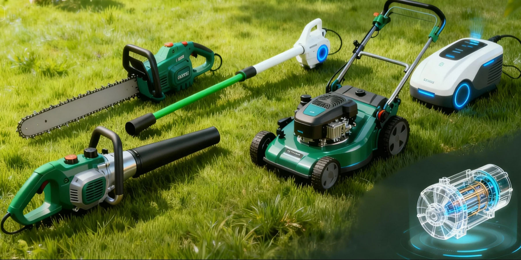
9.6 Power Tools and Garden Equipment
Brushless motor for garden tools has become the dominant technology in premium garden equipment. Cordless lawnmowers, string trimmers, hedge cutters, and leaf blowers all benefit from:
– Longer battery life per charge (higher efficiency)
– Higher power density (more powerful tool in same size)
– Longer tool life (no brush replacement)
ZGC’s lawn mower motor series is specifically engineered for outdoor power equipment, with IP67 waterproof ratings, wide speed ranges, and high starting torque for challenging cutting conditions.
9.7 Medical Devices
Medical applications demand the low EMI, quiet operation, and high reliability of BLDC motors. Surgical robots, dental drills, centrifuges, ventilators, infusion pumps, and MRI-compatible positioning systems all use BLDC technology.
9.8 Aerospace
Actuators, cooling fans, fuel pumps, and attitude control systems in satellites and aircraft use BLDC motors for their reliability and predictable lifespan in environments where maintenance is impossible or prohibitively expensive.
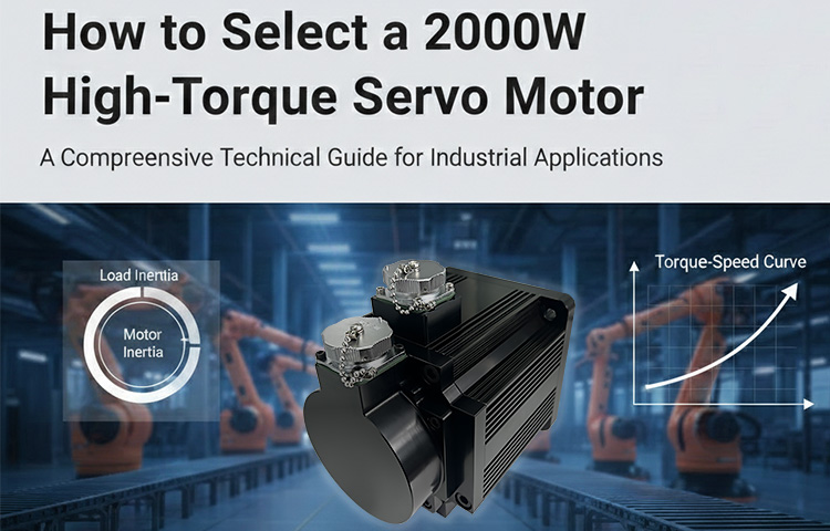
10. How to Select the Right BLDC Motor {#selection-guide}
Selecting a BLDC motor involves systematically working through a series of technical and commercial requirements. Here is a step-by-step selection methodology.
Step 1: Define the Load Profile
Before looking at any motor catalog, characterize your load:
Torque requirements:
– What is the continuous (RMS) torque requirement?
– What is the peak torque required (e.g., for acceleration)?
– Is torque constant, variable, or pulsating?
Speed requirements:
– What is the required operating speed range?
– Is constant speed, variable speed, or positioning required?
– What is the maximum allowable speed?
Duty cycle:
– Continuous operation or intermittent?
– If intermittent, what is the on/off ratio and cycle period?
– For servo applications: what are the acceleration/deceleration profiles?
Inertia:
– What is the load inertia referred to the motor shaft?
– The motor rotor inertia should ideally be within 1–10× the load inertia for good dynamic response (this is the “inertia matching” rule).
Step 2: Define the Power and Voltage
From the torque and speed requirements, calculate required power:
P = T × ω
Where:
– P = Power (W)
– T = Torque (N·m)
– ω = Angular velocity (rad/s) = RPM × π/30
Add a safety margin of 20–30% for thermal headroom and unexpected load variations.
Select a DC bus voltage appropriate for your system. Common considerations:
– Battery-powered systems: match to battery pack voltage (12V, 24V, 48V are common)
– AC-powered systems: rectified 110VAC ≈ 155V DC; rectified 220VAC ≈ 310V DC
– Higher voltage = lower current = thinner wiring = lower drive losses
Step 3: Evaluate Environmental Requirements
Temperature: What are the ambient temperature extremes? Select a motor with appropriate winding insulation class (Class F: 155°C, Class H: 180°C) and verify thermal resistance ensures windings stay within rating.
IP rating: What is the exposure to dust and moisture? Match IP rating to environment—IP65 for typical industrial environments, IP67 for outdoor or wash-down, IP68 for submersion.
Altitude: Above 1,000m, air density decreases and cooling is impaired. Derate accordingly.
Vibration and shock: Select appropriate bearing specifications and consider external vibration sources that might affect encoder accuracy.
Step 4: Select the Motor Configuration
Based on your requirements:
– Inner vs. outer rotor: Inner rotor for high-speed, high-dynamic applications; outer rotor for low-speed, high-torque direct-drive
– Sensored vs. sensorless: Sensored for reliable startup torque and wide speed range; sensorless for simplicity in fan/pump applications
– Integrated vs. separate drive: Integrated for space-saving; separate for maintainability and higher power ratings
– Standard vs. custom: Standard catalog motors cover most applications; custom designs for high-volume OEM applications with specific form factors
Step 5: Verify with Thermal Analysis
Even a perfectly sized motor will fail if it overheats. Verify your selection with a thermal model:
- Calculate RMS phase current from duty cycle and load profile
- Calculate copper losses: P_copper = 3 × I_rms² × R_phase
- Estimate core losses from motor datasheet (if provided)
- Calculate winding temperature rise: ΔT = P_losses × R_thermal
- Verify T_winding_max < thermal rating
Step 6: Verify the Control System Compatibility
Confirm the selected motor is compatible with your intended controller:
– Feedback type compatibility (Hall sensors, encoder type)
– Winding inductance in acceptable range for controller’s PWM frequency
– Communication interface compatibility
– Software/firmware support for motor tuning
Step 7: Commercial Evaluation
Technical fit is necessary but not sufficient. Also evaluate:
– Supply chain: Is the motor in stock or built-to-order? What is lead time?
– Customization: Can the manufacturer accommodate your specific requirements (shaft length, connector type, mounting)?
– Quality certification: ISO 9001, CE, RoHS, UL as required
– Technical support: Does the manufacturer provide application engineering support?
– Long-term availability: Will this motor be available for your product’s lifetime?
As a BLDC motor factory with ISO-certified production and application engineering support, ZGC Motors partners with OEM customers from design to production to ensure long-term supply reliability.
11. BLDC Motor Maintenance and Lifespan {#maintenance}
One of the most compelling arguments for BLDC technology is dramatically reduced maintenance requirements. However, “low maintenance” does not mean “no maintenance.”
11.1 What Wears in a BLDC Motor?
Bearings: The primary wear item in a BLDC motor. Ball bearings have a statistical service life (L10 life) that depends on radial and axial loads, speed, lubrication, and operating temperature. Typical ball bearing L10 life in a properly loaded BLDC motor is 20,000–50,000 hours at moderate speeds.
Signs of bearing wear:
– Increased vibration (check with vibration analyzer)
– Increased acoustic noise (high-frequency whine or rumble)
– Increased operating temperature
– Visible pitting or roughness on bearing races
Hall Sensors: Reliable in normal conditions, but can fail in high-vibration environments or when exposed to extreme temperatures. Failure symptoms include erratic speed, inability to start, or complete motor stoppage.
Winding Insulation: Thermal degradation of winding insulation is the primary cause of motor failure in thermally stressed applications. The Arrhenius rule states that every 10°C increase in operating temperature halves insulation life. Keeping motors within their thermal ratings is therefore critical.
Magnets: Modern NdFeB and ferrite magnets are stable under normal operating conditions. Risks include demagnetization from excessive current (overcurrent protection prevents this), high temperature (above Curie point—well above normal operating range), and physical impact.
11.2 Preventive Maintenance Schedule
For industrial BLDC motor installations:
Every 3–6 months:
– Visual inspection for contamination, damage, unusual temperature
– Vibration measurement baseline comparison
– Check mounting fastener torque
– Verify electrical connections for corrosion or looseness
Every 1–2 years:
– Winding insulation resistance test (megohm test)
– Bearing vibration detailed analysis
– Re-lubrication if using regreasable bearings
– Full functional test including speed regulation accuracy
At end of bearing L10 life:
– Scheduled bearing replacement (preventive vs. reactive)
– Full motor inspection
– Document replacement in maintenance records
11.3 Extending Motor Life
Practical tips for maximizing BLDC motor lifespan:
- Don’t overload: Continuous operation above rated torque/current dramatically reduces insulation life
- Manage temperature: Ensure adequate ventilation or cooling; consider derating in high-ambient environments
- Use appropriate protection: Overcurrent, overvoltage, and thermal shutdown protection prevents catastrophic failures
- Keep it clean: Contamination accelerates bearing wear and can cause insulation failure
- Mount correctly: Misalignment creates radial loads that reduce bearing life
- Select quality bearings: Specify bearing grade and lubrication appropriate to speed and load
12. BLDC Motor Trends in 2025 {#trends}
The BLDC motor industry continues to evolve rapidly. Understanding current trends helps engineers and procurement professionals make forward-looking decisions.
12.1 Higher Efficiency Through Better Materials
The continued development of high-energy permanent magnets is pushing BLDC motor efficiency to new heights. Grade N52 NdFeB magnets now achieve energy products above 50 MGOe. Combined with improved silicon steel laminations (thinner, higher-grade) and optimized winding geometries, motors exceeding 97% peak efficiency are entering commercial production.
12.2 Wide-Bandgap Power Semiconductors in Controllers
Silicon carbide (SiC) and gallium nitride (GaN) power transistors are beginning to replace silicon MOSFETs in high-performance BLDC controllers. Key advantages:
– Switching frequencies 5–10× higher → smaller passive components → more compact drives
– Lower switching losses → higher overall system efficiency
– Higher temperature operation → smaller heatsinks
12.3 AI-Assisted Motor Control
Machine learning algorithms are being integrated into BLDC motor controllers to:
– Automatically identify motor parameters during commissioning
– Adaptively tune PID gains as load conditions change
– Predict bearing failures through vibration pattern analysis
– Optimize efficiency in real time across varying load conditions
12.4 Higher Integration
The boundary between “motor” and “drive” continues to blur. Modern integrated motor-drive units combine motor, encoder, driver, communication module, and even safety function modules in a single assembly, reducing system bill of materials and simplifying machine design.
12.5 Sustainability and Circular Design
Growing regulatory pressure (particularly in the EU) is pushing BLDC motor manufacturers toward:
– Reduced use of heavy rare earth elements (Dy, Tb) in magnets through improved motor geometry
– Design-for-disassembly to enable end-of-life magnet recovery
– Extended product lifespans through improved bearing and insulation designs
– Energy efficiency labeling (IE4, IE5 efficiency classes)
ZGC Motors is actively developing next-generation IE5 efficiency class BLDC motors aligned with IEC 60034-30-2 standards.
12.6 Custom BLDC Motor Manufacturing
As automation spreads into new industries, demand for custom servo motors and application-specific BLDC designs is growing rapidly. Modern manufacturing technology—including CNC winding machines, automated magnetization, and precision assembly robotics—enables economical production of custom designs even at modest volumes (500–5,000 pieces).
ZGC’s engineering team provides full custom motor design services, from initial specification to prototype testing to production scaling.
13. FAQ: Common Questions Answered {#faq}
Q1: What is the difference between a BLDC motor and a servo motor?
A servo motor is not a distinct motor type—it is a control system concept. A servo motor (servo motor) refers to a motor used in a closed-loop position/velocity/torque control system. In modern applications, virtually all servo motors use BLDC motor technology as the electromechanical element, combined with a high-resolution encoder for position feedback and a servo drive implementing FOC for control. So a servo motor IS a BLDC motor, equipped with appropriate feedback and paired with a sophisticated controller.
Q2: Can I run a BLDC motor without a controller?
No. A BLDC motor cannot run without a controller. The controller performs the essential commutation function—without it, no rotating field is generated and the motor will not turn. There is no way to directly connect a BLDC motor to a DC power supply and have it run (unlike a brushed motor, which will spin directly from DC).
Q3: What is the relationship between voltage and speed in a BLDC motor?
BLDC motor speed is approximately proportional to applied voltage. The relationship is characterized by the motor’s back-EMF constant (K_e). At no load: Speed (RPM) ≈ V_supply / K_e. Under load, the speed drops slightly due to resistive voltage drop and commutation losses. The controller manages this by adjusting the effective voltage (PWM duty cycle) to maintain target speed.
Q4: How do I choose between 24V and 48V BLDC motors?
Higher voltage (48V) allows higher power with lower current, which means thinner wiring, smaller connectors, and lower I²R losses. For power levels above 500W, 48V is generally preferred. For below 200W, 24V is often sufficient and may reduce component cost. Safety standards (SELV requirements) consider voltages below 60V DC “safe to touch,” so 48V systems remain within this threshold. Above 60V, additional electrical safety measures are required.
Q5: What does IP67 mean for a BLDC motor?
IP67 means the motor is completely dust-tight (first digit 6) and can be immersed in water up to 1 meter depth for 30 minutes without harmful ingress (second digit 7). This makes IP67-rated waterproof BLDC motors suitable for outdoor equipment, food processing machinery, marine applications, and other wet environments. Note that IP ratings describe protection during static immersion—they do not necessarily guarantee performance during high-pressure jet washing (for which IP69K is the relevant standard).
Q6: How does a BLDC motor compare to a stepper motor?
Stepper motors and BLDC motors are fundamentally different in operation. Stepper motors move in discrete steps (typically 1.8° per step = 200 steps/revolution for NEMA 17) driven by step pulses, with no feedback required for positioning (open-loop). They are simple to use but suffer from resonance, torque loss at high speeds, and energy inefficiency (they maintain holding current even at standstill). BLDC motors operated with FOC and encoders (closed loop stepper motor systems are effectively BLDC-based) outperform open-loop steppers in speed, efficiency, and dynamic performance, at higher system cost.
Q7: What maintenance does a BLDC motor require?
The primary maintenance item is periodic bearing inspection and eventual replacement—typically after 20,000–50,000 hours depending on load and speed. Visual inspection, vibration monitoring, and insulation resistance testing are recommended on a scheduled basis. There is no brush or commutator maintenance. The Hall sensors require no maintenance under normal conditions but may need replacement if damaged.
Q8: Can BLDC motors be used in hazardous (explosive) environments?
Standard BLDC motors are not rated for hazardous environments. For ATEX/IECEx Zone 1 or Zone 2 classified environments, specially designed explosion-proof motors with appropriate certifications are required. Consult a qualified electrical engineer and the relevant safety standards for your region.
Q9: What is a “planetary gear motor” and when is it used with a BLDC motor?
A planetary gear motor combines a BLDC motor with a planetary gearbox. Planetary gearboxes offer high torque density, high efficiency (95–98%), and low backlash in a compact, coaxial form factor. They are used when the application requires higher torque and lower speed than the motor can deliver directly—for example, a mobile robot drive wheel, a linear actuator, or a rotary joint in an industrial robot arm. The gear ratio multiplies output torque while dividing output speed. ZGC’s BLDC gear motor series covers ratios from 3:1 to 100:1 with integrated planetary stages.
Q10: How long does a BLDC motor last?
With proper selection, installation, and maintenance, a quality BLDC motor can operate for 50,000+ hours (approximately 5–6 years of continuous operation or 15–20 years at typical industrial duty cycles). The primary life-limiting factor is bearing wear, which is predictable and manageable through periodic maintenance. Winding insulation failures are preventable through proper thermal management. ZGC motors carry a standard 24-month warranty with expected field lives exceeding 10 years in normal industrial service.
Conclusion
The BLDC motor is not merely a component—it is a platform technology enabling the intelligent, efficient, and connected machines of the modern era. Its combination of high efficiency, long life, compact form, and precise electronic controllability makes it the logical choice for applications ranging from milligram-scale medical actuators to megawatt-scale EV powertrains.
Whether you need a compact inner rotor BLDC motor for a robotics joint, a rugged waterproof BLDC motor for outdoor power equipment, a high-torque outer rotor BLDC motor for a direct-drive application, or a complete integrated motor drive solution for a machine tool, the key to success lies in systematic selection—matching motor characteristics, controller capabilities, and environmental specifications to your precise application requirements.
ZGC Motors has been designing and manufacturing BLDC motors, servo motors, stepper motors, and motor drives for global OEM customers for over a decade. Our engineering team works directly with customers on application analysis, motor selection, customization, and system integration. Whether you need standard catalog products or fully custom servo motors engineered to your exact specifications, we have the technology and manufacturing capability to deliver.
Ready to find the right BLDC motor for your application? Contact our engineering team for a free application consultation, or browse our BLDC motor catalog to explore our full range of standard products.
Keywords: BLDC motor, brushless DC motor, brushless motor, BLDC motor controller, BLDC motor driver, brushless motor drive, outer rotor BLDC motor, inner rotor BLDC motor, high torque BLDC motor, waterproof BLDC motor, FOC motor drive, integrated motor drive, BLDC gear motor, motor with encoder
About ZGC Motors: Changzhou ZGC Mechanical & Electrical Co., Ltd. is a professional BLDC motor manufacturer and servo motor supplier based in Changzhou, China. With ISO 9001 certified production and a full range of standard and custom motor solutions, ZGC serves OEM customers in robotics, industrial automation, electric vehicles, garden tools, and more.